Manufacturers and subsequent distributors of IBCs shall provide information regarding procedures to
be followed and a description of the types and dimensions of closures (including required gaskets) and
any other components needed to ensure that IBCs as presented for carriage are capable of passing the
applicable performance tests of this Chapter.

(Reserved)

(Reserved)

Designatory code system for IBCs

The code shall consist of two Arabic numerals as specified in (a), followed by a capital letter(s)
specified in (b), followed, when specified in an individual section, by an Arabic numeral indicating
the category of IBC.
(a)
 

Type

For solids, filled or discharged


under press

than 10 kPa (0.1 bar)

r liquids

Rigid

11

21

31

Flexible

13

-

-

 
(b)      Materials
 
A.       Steel (all types and surface treatments)
B.       Aluminium
C.        Natural wood
D.       Plywood
F.        Reconstituted wood
G.       Fibreboard
H.       Plastics material
L.       Textile
M.       Paper, multiwall
N.       Metal (other than steel or aluminium).
 

For composite IBCs, two capital letters in Latin characters shall be used in sequence in the second
position of the code. The first shall indicate the material of the inner receptacle of the IBC and the
second that of the outer packaging of the IBC.

The following types and codes of IBC are assigned:


Material

Category

Code

Sub- section

Metal


11A


for solids, filled or discharged under pressure

21A


for liquids

31A


B. Aluminium

for solids, filled or discharged by gravity

11B


for solids, filled or discharged under pressure

21B

6.5.5.1


for liquids

31B


N. Other than steel or aluminium

for solids, filled or discharged by gravity

11N


for solids, filled or discharged under pressure

21N


for liquids

31N


Flexible


H. Plastics

woven plastics without coating or liner

13H1


woven plastics, coated

13H2


woven plastics with liner

13H3


woven plastics, coated and with liner

13H4


plastics film

13H5


L. Textile

without coating or liner

13L1

6.5.5.2


coated

13L2


with liner

13L3


coated and with liner

13L4


M. Paper

multiwall

13M1


multiwall, water resistant

13M2


H. Rigid plastics

for solids, filled or discharged by gravity, fitted with

11H1


s, filled or discharged by gravity, freestanding

11H2


for solids, filled or discharged under pressure, fitted with structural equipment

21H1

6.5.5.3


for solids, filled or discharged under pressure, freestanding

21H2


for liquids, fitted with structural equipment

31H1


for liquids, freestanding

31H2


Material

Category

Code

Sub- section

HZ. Composite

tics inner

for solids, filled or discharged by gravity, with rigid plastics inner receptacle

11HZ1


6.5.5.4

with flexible

11HZ2

for solids, filled or discharged under pressure, with rigid plastics inner receptacle

21HZ1

for solids, filled or discharged under pressure, with flexible plastics inner receptacle

21HZ2

for liquids, with rigid plastics inner receptacle

31HZ1

for liquids, with flexible plastics inner receptacle

31HZ2

G. Fibreboard

for solids, filled or discharged by gravity

11G

6.5.5.5

Wooden

C. Natural wood

for solids, filled or discharged by gravity with inner liner

11C


6.5.5.6

D. Plywood

for solids, filled or discharged by gravity, with inner liner

11D

F. Reconstituted wood

for solids, filled or discharged by gravity, with inner liner

11F

a The code shall be completed by replacing the letter Z by a capital letter in accordance with
6.5.1.4.1 (b) to indicate the nature of the material used for the outer casing.

The letter "W" may follow the IBC code. The letter "W" signifies that the IBC, although of the same
type indicated by the code, is manufactured to a specification different from those in 6.5.5 and is
considered equivalent in accordance with the requirements in 6.5.1.1.2.

Marking

Primary marking

 
Each IBC manufactured and intended for use according to ADR shall bear    marks which are durable,
legible and placed in a location so as to be readily visible. Letters, numerals and symbols shall 
be at least 12 mm high and shall show:
 
 
(a)        The United Nations packaging symbol                                               ;
 
 
This symbol shall not be used for any purpose other than certifying that a packaging, a flexible 
bulk container, a portable tank or a MEGC complies with the relevant  requirements  in  Chapter 
6.1, 6.2, 6.3, 6.5, 6.6, 6.7 or 6.11. For metal IBCs on which the marks are stamped or embossed, 
the capital letters "UN" may be applied instead of the symbol;
 
(b)      The code designating the type of IBC according to 6.5.1.4;
 
(c)      A capital letter designating the packing group(s) for which the design type has been 
approved:
 
(i)       X for packing groups I, II and III (IBCs for solids only);
 
(ii)      Y for packing groups II and III;
 
(iii)     Z for packing group III only;
 
(d)      The month and year (last two digits) of manufacture;
(e) The State authorizing the allocation of the mark; indicated by the distinguishing sign used on 
vehicles in international road traffic1;
(f) The name or symbol of the manufacturer and other identification of the IBC as specified by the 
competent authority;
 
(g)      The stacking test load in kg. For IBCs not designed for stacking, the figure "0" shall be 
shown;
 
(h)      The maximum permissible gross mass in kg.
 
The primary marks required above shall be applied in the sequence of the subparagraphs above. The 
marks required by 6.5.2.2 and any further mark authorized by a competent authority shall still 
enable the primary marks to be correctly identified.
 
Each mark applied in accordance with (a) to (h) and with 6.5.2.2 shall be clearly separated, e.g. 
by a ace, so as to be easily identifiable.


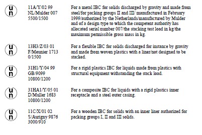
Examples of marking for various types of IBC in accordance with 6.5.2.1.1 (a) to (h) above:


1 Distinguishing sign of the State of registration used on motor vehicles and trailers in international road traffic,
e.g. in accordance with the Geneva Convention on Road Traffic of 1949 or the Vienna Convention on Road Traffic of
1968.

Additional marking

Each IBC shall bear the marks required in 6.5.2.1 and, in addition, the following information which

may appear on a corrosion-resistant plate permanently attached in a place readily accessible for inspection:


Additional marks

Category of IBC

Metal

Rigid plastics

Composite

Fibreboard

Wooden

Capacity in litres at 20 °C

X

X

X


Tare mass in kg a

X

X

X

X

X

Test (gauge) pressure, in kPa or bar a, if applicable


X

X


Maximum filling / discharge pressure in kPa or bar , if applicable

X

X

X


Body material and its minimum thickness in mm

X


Date of last leakproofness test, if applicable (month and year)

X

X

X


Date of last inspection (month and year)

X

X

X


Serial number of the manufacturer

X


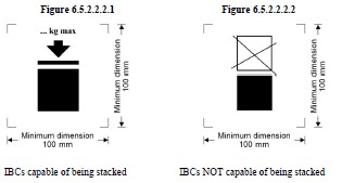
Maximum permitted stacking load b

X

X

X

X

X


 a The unit used shall be indicated.

 b See 6.5.2.2.2. This additional mark shall apply to all IBCs manufactured, repaired or remanufactured as from 1 January 2011 (see also 1.6.1.15).

The maximum permitted stacking load applicable when the IBC is in use shall be displayed on a
symbol as shown in Figure 6.5.2.2.2.1 or Figure 6.5.2.2.2.2. The symbol shall be durable and clearly
visible.


The minimum dimensions shall be 100 mm x 100 mm. The letters and numbers indicating the mass
shall be at least 12 mm high. The area within the printer’s marks indicated by the dimensional arrows
shall be square. Where dimensions are not specified, all features shall be in approximate proportion to
those shown. The mass marked above the symbol shall not exceed the load imposed during the design
type test (see 6.5.6.6.4) divided by 1.8.


Previous Matter Next Matter

adrbook.com - Copyright all rights reserved. © 2015-2018