Each IBC shall bear the marks required in 6.5.2.1 and, in addition, the following information which
may appear on a corrosion-resistant plate permanently attached in a place readily accessible for inspection:
|
Additional marks
|
Category of IBC
|
|
Metal
|
Rigid plastics
|
Composite
|
Fibreboard
|
Wooden
|
|
Capacity in litres a at 20 °C
|
X
|
X
|
X
|
|
|
|
Tare mass in kg a
|
X
|
X
|
X
|
X
|
X
|
|
Test (gauge) pressure, in kPa or bar a, if applicable
|
|
X
|
X
|
|
|
|
Maximum filling / discharge pressure in kPa or bar a , if applicable
|
X
|
X
|
X
|
|
|
|
Body material and its minimum thickness in mm
|
X
|
|
|
|
|
|
Date of last leakproofness test, if applicable (month and year)
|
X
|
X
|
X
|
|
|
|
Date of last inspection (month and year)
|
X
|
X
|
X
|
|
|
|
Serial number of the manufacturer
|
X
|
|
|
|
|
|
Maximum permitted stacking load b
|
X
|
X
|
X
|
X
|
X
|
a The unit used shall be indicated.
b See 6.5.2.2.2. This additional mark shall apply to all IBCs manufactured, repaired or remanufactured as from 1 January 2011 (see also 1.6.1.15).
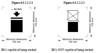
The maximum permitted stacking load applicable when the IBC is in use shall be displayed on a
symbol as shown in Figure 6.5.2.2.2.1 or Figure 6.5.2.2.2.2. The symbol shall be durable and clearly
visible.
The minimum dimensions shall be 100 mm x 100 mm. The letters and numbers indicating the mass
shall be at least 12 mm high. The area within the printer’s marks indicated by the dimensional arrows
shall be square. Where dimensions are not specified, all features shall be in approximate proportion to
those shown. The mass marked above the symbol shall not exceed the load imposed during the design
type test (see 6.5.6.6.4) divided by 1.8.
In addition to the marks required in 6.5.2.1, flexible IBCs may bear a pictogram indicating
recommended lifting methods.
Inner receptacles that are of composite IBC design type shall be identified by the application of the
marks indicated in 6.5.2.1.1 (b), (c), (d) where this date is that of the manufacture of the plastics inner
receptacle, (e) and (f). The UN packaging symbol shall not be applied. The marks shall be applied in
the sequence shown in 6.5.2.1.1. It shall be durable, legible and placed in a location so as to be readily
visible when the inner receptacle is placed in the outer casing.
The date of the manufacture of the plastics inner receptacle may alternatively be marked on the inner
receptacle adjacent to the remainder of the marks. In such a case, the two digits of the year in the mark
and in the inner circle of the clock shall be identical. An example of an appropriate marking method
is:
NOTE 1: Other methods that provide the minimum required information in a durable, visible and
legible form are also acceptable.
NOTE 2: The date of manufacture of the inner receptacle may be different from the marked date of
manufacture (see 6.5.2.1), repair (see 6.5.4.5.3) or remanufacture (see 6.5.2.4) of the composite IBC.
Where a composite IBCs is designed in such a manner that the outer casing is intended to be
dismantled for carriage when empty (such as for return of the IBC for reuse to the original consignor),
each of the parts intended to be detached when so dismantled shall be marked with the month and year
of manufacture and the name or symbol of the manufacturer and other identification of the IBC as
specified by the competent authority (see 6.5.2.1.1 (f)).
Conformity to design type
The marks indicate that IBCs correspond to a successfully tested design type and that the requirements
referred to in the certificate have been met.
Marking of remanufactured composite IBCs (31HZ1)
The marks specified in 6.5.2.1.1 and 6.5.2.2 shall be removed from the original IBC or made
permanently illegible and new marks shall be applied to an IBC remanufactured in accordance with
ADR.
Construction requirements
General requirements
IBCs shall be resistant to or adequately protected from deterioration due to the external environment.
IBCs shall be so constructed and closed that none of the contents can escape under normal conditions
of carriage including the effect of vibration, or by changes in temperature, humidity or pressure.
IBCs and their closures shall be constructed of materials compatible with their contents, or be
protected internally, so that they are not liable:
(a) To be attacked by the contents so as to make their use dangerous;
(b) To cause the contents to react or decompose, or form harmful or dangerous compounds with
the IBCs.
Gaskets, where used, shall be made of materials not subject to attack by the contents of the IBCs.
All service equipment shall be so positioned or protected as to minimize the risk of escape of the
contents owing to damage during handling and carriage.
IBCs, their attachments and their service and structural equipment shall be designed to withstand,
without loss of contents, the internal pressure of the contents and the stresses of normal handling and
carriage. IBCs intended for stacking shall be designed for stacking. Any lifting or securing features of
IBCs shall be of sufficient strength to withstand the normal conditions of handling and carriage
without gross distortion or failure and shall be so positioned that no undue stress is caused in any part
of the IBC.