It shall be noted that the pressure-relief devices shall operate only in conditions of excessive rise in
temperature, since the shell shall not be subject to undue fluctuations of pressure during normal
conditions of carriage (see 6.7.2.12.2).
The required pressure-relief device shall be set to start-to-discharge at a nominal pressure of
five-sixths of the test pressure for shells having a test pressure of not more than 4.5 bar and 110% of
two-thirds of the test pressure for shells having a test pressure of more than 4.5 bar. After discharge
the device shall close at a pressure not more than 10% below the pressure at which the discharge
starts. The device shall remain closed at all lower pressures. This requirement does not prevent the use
of vacuum-relief or combination pressure-relief and vacuum-relief devices.
Fusible elements
Fusible elements shall operate at a temperature between 100 °C and 149 °C on condition that the
pressure in the shell at the fusing temperature will be not more than the test pressure. They shall be
placed at the top of the shell with their inlets in the vapour space and when used for transport safety
purposes, they shall not be shielded from external heat. Fusible elements shall not be used on portable
tanks with a test pressure which exceeds 2.65 bar unless specified by special provision TP36 in
Column (11) of Table A of Chapter 3.2. Fusible elements used on portable tanks intended for the
carriage of elevated temperature substances shall be designed to operate at a temperature higher than
the maximum temperature that will be experienced during carriage and shall be to the satisfaction of
the competent authority or its authorized body.
Frangible discs
Except as specified in 6.7.2.8.3, frangible discs shall be set to rupture at a nominal pressure equal to
the test pressure throughout the design temperature range. Particular attention shall be given to the
requirements of 6.7.2.5.1 and 6.7.2.8.3 if frangible discs are used.
Frangible discs shall be appropriate for the vacuum pressures which may be produced in the portable
tank.
Capacity of pressure-relief devices
The spring-loaded pressure-relief device required by 6.7.2.8.1 shall have a minimum cross sectional
flow area equivalent to an orifice of 31.75 mm diameter. Vacuum-relief devices, when used, shall
have a cross sectional flow area not less than 284 mm2.
The combined delivery capacity of the pressure relief system (taking into account the reduction of the
flow when the portable tank is fitted with frangible-discs preceding spring-loaded pressure-relief
devices or when the spring-loaded pressure-relief devices are provided with a device to prevent the
passage of the flame), in condition of complete fire engulfment of the portable tank shall be sufficient
to limit the pressure in the shell to 20% above the start-to-discharge pressure of the pressure limiting
device. Emergency pressure-relief devices may be used to achieve the full relief capacity prescribed.
These devices may be fusible, spring loaded or frangible disc components, or a combination of springloaded
and frangible disc devices. The total required capacity of the relief devices may be determined
using the formula in 6.7.2.12.2.1 or the table in 6.7.2.12.2.3.
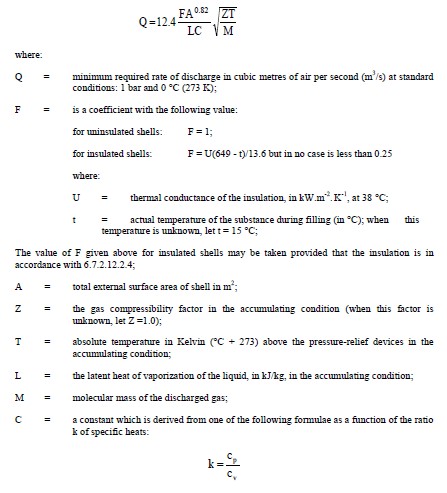
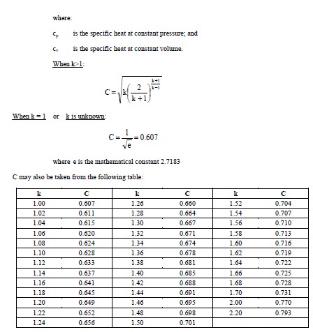
To determine the total required capacity of the relief devices, which shall be regarded as being the
sum of the individual capacities of all the contributing devices, the following formula shall be used:
As an alternative to the formula above, shells designed for the carriage of liquids may have their relief
devices sized in accordance with the table in 6.7.2.12.2.3. This table assumes an insulation value of
F = 1 and shall be adjusted accordingly when the shell is insulated. Other values used in determining
this table are:
M = 86,7 T = 394 K
L = 334,94 kJ/kg C = 0,607
Z = 1
Minimum required rate of discharge, Q, in cubic metres per air per second at 1 bar and 0 °C (273 K)
|
A
Exposed area (square metres)
|
Q
(cubic metres of air per second)
|
A
Exposed area (square metres)
|
Q
(cubic metres of air per second)
|
|
2
|
0.230
|
37.5
|
2.539
|
|
3
|
0.320
|
40
|
2.677
|
|
4
|
0.405
|
42.5
|
2.814
|
|
5
|
0.487
|
45
|
2.949
|
|
6
|
0.565
|
47.5
|
3.082
|
|
7
|
0.641
|
50
|
3.215
|
|
8
|
0.715
|
52.5
|
3.346
|
|
9
|
0.788
|
55
|
3.476
|
|
A
Exposed area (square metres)
|
Q
(cubic metres of air per second)
|
A
Exposed area (square metres)
|
Q
(cubic metres of air per second)
|
|
10
|
0.859
|
57.5
|
3.605
|
|
12
|
0.998
|
60
|
3.733
|
|
14
|
1.132
|
62.5
|
3.860
|
|
16
|
1.263
|
65
|
3.987
|
|
18
|
1.391
|
67.5
|
4.112
|
|
20
|
1.517
|
70
|
4.236
|
|
22.5
|
1.670
|
75
|
4.483
|
|
25
|
1.821
|
80
|
4.726
|
|
27.5
|
1.969
|
85
|
4.967
|
|
30
|
2.115
|
90
|
5.206
|
|
32.5
|
2.258
|
95
|
5.442
|
|
35
|
2.400
|
100
|
5.676
|
Insulation systems, used for the purpose of reducing venting capacity, shall be approved by the
competent authority or its authorized body. In all cases, insulation systems approved for this purpose
shall:
(a) Remain effective at all temperatures up to 649 °C; and
(b) Be jacketed with a material having a melting point of 700 °C or greater.
Marking of pressure-relief devices
Previous Matter
Next Matter