Dangerous Goods by Road
|
The tanks and their fastenings shall be capable of
absorbing, under the maximum permissible load,
the forces exerted by:
- in the direction of travel: twice the total
mass;
- at right angles to the direction of travel: the
total mass;
- vertically upwards: the total mass;
- vertically downwards: twice the total mass.
|
Tank-containers and their fastenings shall,
under the maximum permissible load be
capable of absorbing the forces equal to those
exerted by:
- in the direction of travel: twice the total
mass;
- horizontally at right angles to the direction
of travel: the total mass; (where the
direction of travel is not clearly
determined, twice the total mass in each
direction);
- vertically upwards: the total mass;
- vertically downwards: twice the total
mass.
|
The walls of the shells shall have at least the thickness specified in
| 6.8.2.1.17 to 6.8.2.1.21 | 6.8.2.1.17 to 6.8.2.1.20. |
Shells shall be designed and constructed in accordance with the requirements of standards listed in
6.8.2.6 or of a technical code recognized by the competent authority, in accordance with 6.8.2.7, in
which the material is chosen and the shell thickness determined taking into account maximum and
minimum filling and working temperatures, but the following minimum requirements of 6.8.2.1.6 to
6.8.2.1.26 shall be met.
Tanks intended to contain certain dangerous substances shall be provided with additional protection.
This may take the form of additional thickness of the shell (increased calculation pressure) determined
in the light of the dangers inherent in the substances concerned or of a protective device (see the
special provisions of 6.8.4).
Welds shall be skilfully made and shall afford the fullest safety. The execution and checking of welds
shall comply with the requirements of 6.8.2.1.23.
Measures shall be taken to protect shells against the risk of deformation as a result of a negative
internal pressure. Shells, other than shells according to 6.8.2.2.6, designed to be equipped with
vacuum valves shall be able to withstand, without permanent deformation, an external pressure of not
less than 21 kPa (0.21 bar) above the internal pressure. Shells used for the carriage of solid substances
(powdery or granular) of packing groups II or III only, which do not liquefy during carriage, may be
designed for a lower external pressure but not less than 5 kPa (0.05 bar). The vacuum valves shall be
set to relieve at a vacuum setting not greater than the tank's design vacuum pressure. Shells, which are
not designed to be equipped with a vacuum valve shall be able to withstand, without permanent
deformation an external pressure of not less than 40 kPa (0.4 bar) above the internal pressure.
Materials for shells
Shells shall be made of suitable metallic materials which, unless other temperature ranges are
prescribed in the various classes, shall be resistant to brittle fracture and to stress corrosion cracking
between -20 °C and +50 °C.
The materials of shells or of their protective linings which are in contact with the contents shall not
contain substances liable to react dangerously (see "Dangerous reaction" in 1.2.1) with the contents, to
form dangerous compounds, or substantially to weaken the material.
If contact between the substance carried and the material used for the construction of the shell entails
a progressive decrease in the shell thickness, this thickness shall be increased at manufacture by an
appropriate amount. This additional thickness to allow for corrosion shall not be taken into
consideration in calculating the shell thickness.
For welded shells only materials of faultless weldability whose adequate impact strength at an ambient
temperature of –20 ºC can be guaranteed, particularly in the weld seams and the zones adjacent
thereto, shall be used.
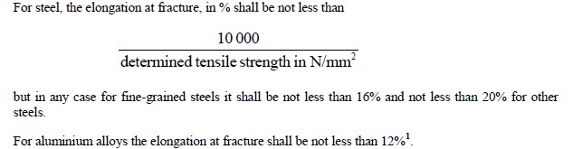
If fine-grained steel is used, the guaranteed value of the yield strength Re shall not exceed 460 N/mm2
and the guaranteed value of the upper limit of tensile strength Rm shall not exceed 725 N/mm2, in
accordance with the specifications of the material.
Ratios of Re/Rm exceeding 0.85 are not allowed for steels used in the construction of welded tanks.
Re = apparent yield strength for steels having a clearly-defined yield point or
guaranteed 0.2% proof strength for steels with no clearly-defined yield point (1% for
austenitic steels)
Rm = tensile strength.
The values specified in the inspection certificate for the material shall be taken as a basis in
determining this ratio in each case.
Calculation of the shell thickness
The pressure on which the shell thickness is based shall not be less than the calculation pressure, but
the stresses referred to in 6.8.2.1.1 shall also be taken into account, and, if necessary, the following
stresses:
|
In the case of vehicles in which the tank
constitutes a stressed self-supporting member,
the shell shall be designed to withstand the
stresses thus imposed in addition to stresses from
other sources.
Under these stresses, the stress at the most
severely stressed point of the shell and its
fastenings shall not exceed the value σ defined in
6.8.2.1.16.
|
Under each of these stresses the safety factors to
be observed shall be the following:
- for metals having a clearly-defined yield
point: a safety factor of 1.5 in relation to the
apparent yield strength; or
- for metals with no clearly-defined yield
point: a safety factor of 1.5 in relation to the
guaranteed 0.2% proof strength
(1% maximum elongation for austenitic
steels).
|
1 In the case of sheet metal the axis of the tensile test-piece shall be at right angles to the direction of rolling. The
permanent elongation at fracture shall be measured on test-pieces of circular cross-section in which the gauge length l
is equal to five times the diameter d (l = 5d); if test-pieces of rectangular section are used, the gauge length shall be
calculated by the formula
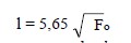
where Fo indicates the initial cross-section area of the test-piece.
The calculation pressure is in the second part of the code (see 4.3.4.1) according to Column (12) of
Table A of Chapter 3.2.
When "G" appears, the following requirements shall apply:
(a) Gravity-discharge shells intended for the carriage of substances having a vapour pressure not
exceeding 110 kPa (1.1 bar) (absolute pressure) at 50 ºC shall be designed for a calculation
pressure of twice the static pressure of the substance to be carried but not less than twice the
static pressure of water;
(b) Pressure-filled or pressure-discharge shells intended for the carriage of substances having a
vapour pressure not exceeding 110 kPa (1.1 bar) (absolute pressure) at 50 ºC shall be designed
for a calculation pressure equal to 1.3 times the filling or discharge pressure;
When the numerical value of the minimum calculation pressure is given (gauge pressure) the shell
shall be designed for this pressure which shall not be less than 1.3 times the filling or discharge
pressure. The following minimum requirements shall apply in these cases:
(c) Shells intended for the carriage of substances having a vapour pressure of more than 110 kPa
(1.1 bar) at 50 °C and a boiling point of more than 35 °C shall, whatever their filling or
discharge system, be designed for a calculation pressure of not less than 150 kPa (1.5 bar)
gauge pressure or 1.3 times the filling or discharge pressure, whichever is the higher;
(d) Shells intended for the carriage of substances having a boiling point of not more than 35 °C
shall, whatever their filling or discharge system, be designed for a calculation pressure equal to
1.3 times the filling or discharge pressure but not less than 0.4 MPa (4 bar) (gauge pressure).
At the test pressure, the stress σ at the most severely stressed point of the shell shall not exceed the
material-dependent limits prescribed below. Allowance shall be made for any weakening due to the
welds.
For all metals and alloys, the stress σ at the test pressure shall be lower than the smaller of the values
given by the following formulae:
σ ≤ 0.75 Re or σ ≤ 0.5 Rm
where
Re = apparent yield strength for steels having a clearly-defined yield point; or
guaranteed 0.2% proof strength for steels with no clearly-defined yield point (1% for
austenitic steels)
Rm = tensile strength.
The values of Re and Rm to be used shall be specified minimum values according to material
standards. If no material standard exists for the metal or alloy in question, the values of Re and
Rm used shall be approved by the competent authority or by a body designated by that
authority.
When austenitic steels are used, the specified minimum values according to the material standards
may be exceeded by up to 15% if these higher values are attested in the inspection certificate. The
minimum values shall, however, not be exceeded when the formula given in 6.8.2.1.18 is applied.