Materials for shells
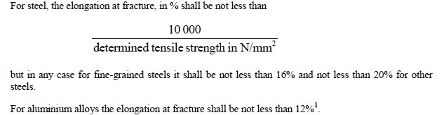
Calculation of the shell thickness
|
In the case of vehicles in which the tank
constitutes a stressed self-supporting member,
the shell shall be designed to withstand the
stresses thus imposed in addition to stresses from
other sources.
Under these stresses, the stress at the most
severely stressed point of the shell and its
fastenings shall not exceed the value σ defined in
6.8.2.1.16.
|
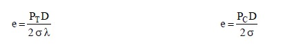
Under each of these stresses the safety factors to
be observed shall be the following:
- for metals having a clearly-defined yield
point: a safety factor of 1.5 in relation to the
apparent yield strength; or
- for metals with no clearly-defined yield
point: a safety factor of 1.5 in relation to the
guaranteed 0.2% proof strength
(1% maximum elongation for austenitic
steels).
|
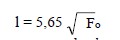
where Fo indicates the initial cross-section area of the test-piece.
Minimum shell thickness
The thickness shall in no case be less than that defined in
| 6.8.2.1.18 to 6.8.2.1.21. | 6.8.2.1.18 to 6.8.2.1.20. |
|
Shells of circular cross-section 2 not more than
1.80 m in diameter other than those referred to in
6.8.2.1.21, shall not be less than 5 mm thick if of
mild steel3, or of equivalent thickness if of
another metal.
Where the diameter is more than 1.80 m, this
thickness shall be increased to 6 mm except in
the case of shells intended for the carriage of
powdery or granular substances, if the shell is of
mild steel3, or to an equivalent thickness if of
another metal.
|
Shells shall be not less than 5 mm thick if of mild
steel3 (in conformity with the requirements of
6.8.2.1.11 and 6.8.2.1.12) or of equivalent
thickness if of another metal.
Where the diameter is more than 1.80 m, this
thickness shall be increased to 6 mm except in
the case of tanks intended for the carriage of
powdery or granular substances, if the shell is of
mild steel3 or to an equivalent thickness if of
another metal.
Whatever the metal used, the shell thickness
shall in no case be less than 3 mm.
|
|
Where protection of the tank against damage
through lateral impact or overturning is provided
according to 6.8.2.1.20, the competent authority
may allow the aforesaid minimum thicknesses to
be reduced in proportion to the protection
provided; however, the said thicknesses shall not
be less than 3 mm in the case of mild steel3, or
than an equivalent thickness in the case of other
materials, for shells not more than 1.80 m in
diameter. For shells with a diameter exceeding
1.80 m the aforesaid minimum thickness shall be
increased to 4 mm in the case of mild steel3 and
to an equivalent thickness in the case of other
metals.
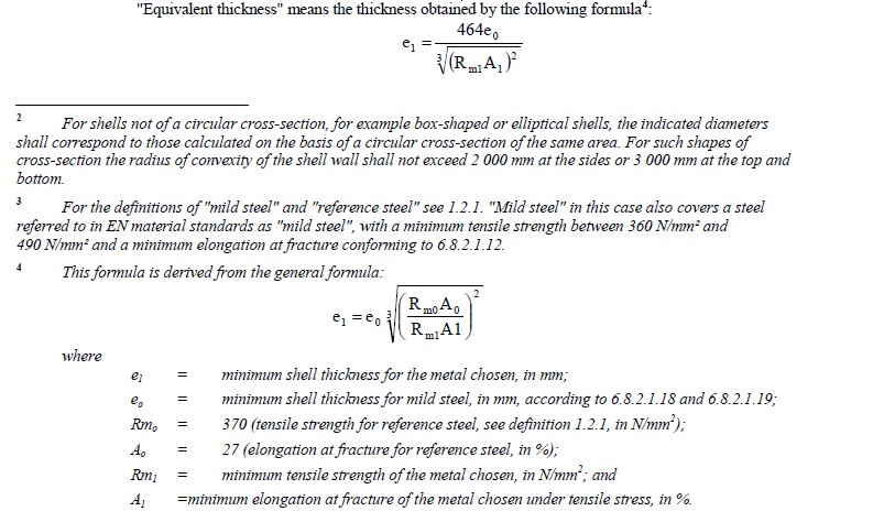
Equivalent thickness means the thickness given
by the formula in 6.8.2.1.18.
Except in cases for which 6.8.2.1.21 provide, the
thickness of shells with protection against
damage in accordance with 6.8.2.1.20 (a) or (b)
shall not be less than the values given in the
table below.
|
Where protection of the tank against damage is
provided according to 6.8.2.1.20, the competent
authority may allow the aforesaid minimum
thicknesses to be reduced in proportion to the
protection provided; however, the said
thicknesses shall be not less than 3 mm in the
case of mild steel3, or than an equivalent
thickness in the case of other materials, for shells
not more than 1.80 m in diameter. For shells of a
diameter exceeding 1.80 m this minimum
thickness shall be increased to 4 mm in the case
of mild steel3, and to an equivalent thickness in
the case of other metals.
Equivalent thickness means the thickness given
by the formula in 6.8.2.1.18.
The thickness of shells with protection against
damage in accordance with 6.8.2.1.20 shall not
be less than the values given in the table below.
|
|
Diameter of shell |
≤ 1,80 m |
> 1,80 m |
||
|
Minimum
thickness of
shells
|
Austenitic stainless steels | 2,5 mm |
3 mm |
|
|
Austenitic-ferritic stainless
steels
|
3 mm |
3,5 mm |
||
| Other steels |
3 mm |
4 mm |
||
|
Aluminium alloys |
4 mm |
5 mm |
||
|
Pure aluminium of 99.80% |
6 mm |
8 mm |
||
|
For tanks built after 1 January 1990, there is
protection against damage as referred to in
6.8.2.1.19 when the following measures or
equivalent5 measures are adopted:
(a) For tanks intended for the carriage of
powdery or granular substances, the
protection against damage shall satisfy the
competent authority.
(b) For tanks intended for the carriage of other
substances, there is protection against
damage when:
1. For shells with a circular or elliptical
cross-section having a maximum radius
of curvature of 2 m, the shell is
equipped with strengthening members
comprising partitions, surge-plates or
external or internal rings, so placed that
at least one of the following conditions
is met:
- Distance between two adjacent
strengthening elements of not more
than 1.75 m.
- Volume contained between two
partitions or surge-plates of not
more than 7 500 l.
The vertical cross-section of a ring,
with the associated coupling, shall have
a section modulus of at least 10 cm3.
External rings shall not have projecting
edges with a radius of less than
2.5 mm.
Partitions and surge-plates shall
conform to the requirements of
6.8.2.1.22.
The thickness of the partitions and
surge-plates shall in no case be less
than that of the shell.
2. For tanks made with double walls, the
space between being evacuated of air,
the aggregate thickness of the outer
metal wall and the shell wall
corresponds to the wall thickness
prescribed in 6.8.2.1.18, and the
thickness of the wall of the shell itself
is not less than the minimum thickness
prescribed in 6.8.2.1.19.
3. For tanks made with double walls
having an intermediate layer of solid
materials at least 50 mm thick, the
outer wall has a thickness of at least
0.5 mm of mild steel3 or at least 2 mm
of a plastics material reinforced with
glass fibre. Solid foam (with an impact
absorption capacity like that, for
example, of polyurethane foam) may be
used as the intermediate layer of solid
material.
4. Shells of forms other than in 1,
especially box-shaped shells, are
provided, all round the mid-point of
their vertical height and over at least
30% of their height with a protection
designed in such a way as to offer
specific resilience at least equal to that
of a shell constructed in mild steel3 of a
thickness of 5 mm (for a shell diameter
not exceeding 1.80 m) or 6 mm (for a
shell diameter exceeding 1.80 m). The
protection shall be applied in a durable
manner to the shell.
This requirement shall be considered to
have been met without further proof of
the specific resilience when the
protection involves the welding of a
plate of the same material as the shell to
the area to be strengthened, so that the
minimum wall thickness is in
accordance with 6.8.2.1.18.
This protection is dependent upon the
possible stresses exerted on mild steel3
shells in the event of an accident, where
the ends and walls have a thickness of
at least 5 mm for a diameter not
exceeding 1.80 m or at least 6 mm for a
diameter exceeding 1.80 m. If another
metal is used, the equivalent thickness
shall be obtained in accordance with the
formula in 6.8.2.1.18.
For demountable tanks this protection is not
required when they are protected on all sides by
the drop sides of the carrying vehicle.
|
The protection referred to in 6.8.2.1.19 may
consist of:
- overall external structural protection as in
"sandwich" construction where the sheathing
is secured to the shell; or
- a structure in which the shell is supported by a
complete skeleton including longitudinal and
transverse structural members; or
- double-wall construction.
Where the tanks are made with double walls, the
space between being evacuated of air, the
aggregate thickness of the outer metal wall and
the shell wall shall correspond to the minimum
wall thickness prescribed in 6.8.2.1.18, the
thickness of the wall of the shell itself being not
less than the minimum thickness prescribed in
6.8.2.1.19.
Where tanks are made with double walls with an
intermediate layer of solid materials at least
50 mm thick, the outer wall shall have a
thickness of not less than 0.5 mm if it
is made of mild steel3 or at least 2 mm if it is
made of a plastics material reinforced with glass
fibre. Solid foam with an impact absorption
capacity such as that, for example, of
polyurethane foam, may be used as the
intermediate layer of solid material.
|
|
The thickness of shells designed in accordance with 6.8.2.1.14 (a) which either are of not more than 5 000 litres capacity or are divided into leakproof compartments of not more than 5 000 litres unit capacity may be adjusted to a level which, unless prescribed otherwise in 6.8.3 or 6.8.4, shall however not be less than the appropriate value shown in the following table: |
|
Maximum radius of curvature of shell (m) |
Capacity of shell or shell compartment (m3) |
Minimum thickness (mm) |
|
Mild steel |
||
|
2 |
5.0 |
3 |
|
2 - 3 |
3.5 |
3 |
|
|
> 3.5 but 5.0 |
4 |
|
Where a metal other than mild steel3 is used, the thickness shall be determined by the equivalence formula given in 6.8.2.1.18 and shall not be less than the values given in the following table: |
||||
|
|
|
|||
|
|
Maximum radius of curvature of shell (m) |
2 |
2-3 |
2-3 |
|
Capacity of shell or shell compartment (m3) |
5.0 |
3.5 |
> 3.5 but 5.0 |
|
|
Minimum thickness of shell |
Austenitic stainless steels |
2.5 mm |
2.5 mm |
3 mm |
|
Austenitic- ferritic stainless steels |
3 mm |
3 mm |
3.5 mm |
|
|
Other steels |
3 mm |
3 mm |
4 mm |
|
|
Aluminium alloys |
4 mm |
4 mm |
5 mm |
|
|
Pure aluminium at 99.80% |
6 mm |
6 mm |
8 mm |
|