Dangerous Goods by Road
Pressure-relief devices
Portable tanks shall be provided with one or more spring-loaded pressure-relief devices. The pressurerelief
devices shall open automatically at a pressure not less than the MAWP and be fully open at a
pressure equal to 110% of the MAWP. These devices shall, after discharge, close at a pressure not
lower than 10% below the pressure at which discharge starts and shall remain closed at all lower
pressures. The pressure-relief devices shall be of a type that will resist dynamic forces including liquid
surge. Frangible discs not in series with a spring-loaded pressure-relief device are not permitted.
Pressure-relief devices shall be designed to prevent the entry of foreign matter, the leakage of gas and
the development of any dangerous excess pressure.
Portable tanks intended for the carriage of certain non-refrigerated liquefied gases identified in
portable tank instruction T50 in 4.2.5.2.6 shall have a pressure-relief device approved by the
competent authority. Unless a portable tank in dedicated service is fitted with an approved relief
device constructed of materials compatible with the load, such device shall comprise a frangible disc
preceding a spring-loaded device. The space between the frangible disc and the device shall be
provided with a pressure gauge or a suitable tell-tale indicator. This arrangement permits the detection
of disc rupture, pinholing or leakage which could cause a malfunction of the pressure-relief device.
The frangible discs shall rupture at a nominal pressure 10% above the start-to-discharge pressure of
the relief device.
In the case of multi-purpose portable tanks, the pressure-relief devices shall open at a pressure
indicated in 6.7.3.7.1 for the gas having the highest maximum allowable pressure of the gases allowed
to be carried in the portable tank.
Capacity of relief devices
The combined delivery capacity of the relief devices shall be sufficient that, in the event of total fire
engulfment, the pressure (including accumulation) inside the shell does not exceed 120% of the
MAWP. Spring-loaded relief devices shall be used to achieve the full relief capacity prescribed. In the
case of multi-purpose tanks, the combined delivery capacity of the pressure-relief devices shall be
taken for the gas which requires the highest delivery capacity of the gases allowed to be carried in
portable tanks.
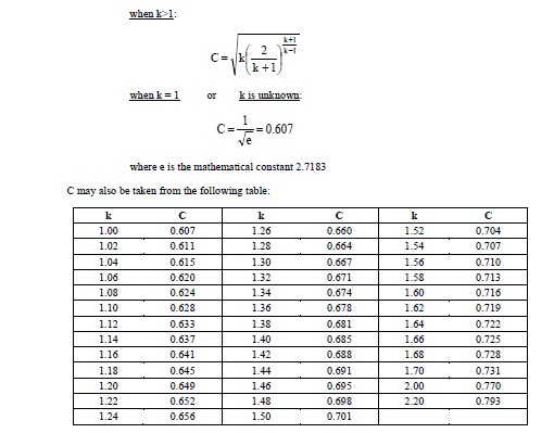
To determine the total required capacity of the relief devices, which shall be regarded as being the
sum of the individual capacities of the several devices, the following formula5 shall be used:
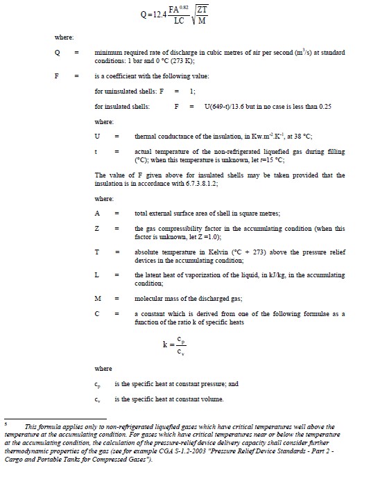
Insulation systems, used for the purpose of reducing the venting capacity, shall be approved by the
competent authority or its authorized body. In all cases, insulation systems approved for this purpose
shall:
(a) Remain effective at all temperatures up to 649 °C; and
(b) Be jacketed with a material having a melting point of 700 °C or greater.
Marking of pressure-relief devices
Every pressure-relief device shall be plainly and permanently marked with the following particulars:
(a) The pressure (in bar or kPa) at which it is set to discharge;
(b) The allowable tolerance at the discharge pressure for spring-loaded devices;
(c) The reference temperature corresponding to the rated pressure for frangible discs;
(d) The rated flow capacity of the device in standard cubic metres of air per second (m3/s); and
(e) The cross sectional flow areas of the spring loaded pressure-relief devices and frangible discs
in mm².
When practicable, the following information shall also be shown:
(f) The manufacturer's name and relevant catalogue number of the device.
The rated flow capacity marked on the pressure-relief devices shall be determined according to
ISO 4126-1:2004 and ISO 4126-7:2004.
Connections to pressure-relief devices
Connections to pressure-relief devices shall be of sufficient size to enable the required discharge to
pass unrestricted to the safety device. No stop-valve shall be installed between the shell and the
pressure-relief devices except when duplicate devices are provided for maintenance or other reasons
and the stop-valves serving the devices actually in use are locked open or the stop-valves are
interlocked so that at least one of the duplicate devices is always operable and capable of meeting the
requirements of 6.7.3.8. There shall be no obstruction in an opening leading to a vent or
pressure-relief device which might restrict or cut-off the flow from the shell to that device. Vents from
the pressure-relief devices, when used, shall deliver the relieved vapour or liquid to the atmosphere in
conditions of minimum back-pressure on the relieving device.