Dangerous Goods by Road
Raw materials
All materials used for the manufacture of FRP tanks shall be of known origin and specifications.
Resins
The processing of the resin mixture shall be carried out in strict compliance with the recommendations
of the supplier. This concerns mainly the use of hardeners, initiators and accelerators. These resins can
be:
- unsaturated polyester resins;
- vinyl ester resins;
- epoxy resins;
- phenolic resins.
The heat distortion temperature (HDT) of the resin, determined in accordance with EN ISO 75-1:2013
shall be at least 20°C higher than the maximum service temperature of the tank, but shall in any case
not be lower than 70 °C.
Reinforcement fibres
The reinforcement material of the structural layers shall be a suitable grade of fibres such as glass
fibres of type E or ECR according to ISO 2078:1993. For the internal surface liner, glass fibres of type
C according to ISO 2078:1993 may be used. Thermoplastic veils may only be used for the internal
liner when their compatibility with the intended contents has been demonstrated.
Thermoplastic liner material
Thermoplastic liners, such as unplastified polyvinyl chloride (PVC-U), polypropylene (PP),
polyvinylidene fluoride (PVDF), polytetrafluoroethylene (PTFE), etc. may be used as lining materials.
Additives
Additives necessary for the treatment of the resin, such as catalysts, accelerators, hardeners and
thixotropic substances as well as materials used to improve the tank, such as fillers, colours, pigments
etc. shall not cause weakening of the material, taking into account lifetime and temperature
expectancy of the design.
Shells, their attachments and their service and structural equipment shall be designed to withstand
without loss of contents (other than quantities of gas escaping through any degassing vents) during the
design lifetime:
- the static and dynamic loads in normal conditions of carriage;
- the prescribed minimum loads as defined in 6.9.2.5 to 6.9.2.10.
At the pressures as indicated in 6.8.2.1.14 (a) and (b), and under the static gravity forces caused by the
contents with maximum density specified for the design and at maximum filling degree, the design
stress σ in longitudinal and circumferential direction of any layer of the shell shall not exceed the
following value:
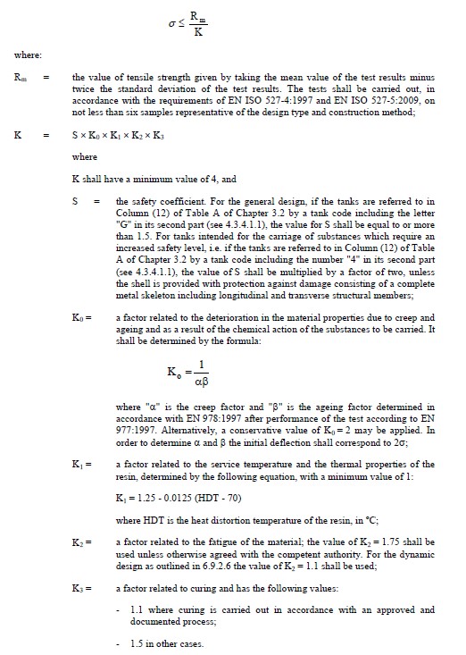
At the dynamic stresses, as indicated in 6.8.2.1.2 the design stress shall not exceed the value specified
in 6.9.2.5, divided by the factor α.
At any of the stresses as defined in 6.9.2.5 and 6.9.2.6, the resulting elongation in any direction shall
not exceed 0.2% or one tenth of the elongation at fracture of the resin, whichever is lower.
At the specified test pressure, which shall not be less than the relevant calculation pressure as
specified in 6.8.2.1.14 (a) and (b) the maximum strain in the shell shall not be greater than the
elongation at fracture of the resin.
The shell shall be capable of withstanding the ball drop test according to 6.9.4.3.3 without any visible
internal or external defects.
The overlay laminates used in the joints, including the end joints, the joints of the surge plates and the
partitions with the shell shall be capable of withstanding the static and dynamic stresses mentioned
above. In order to avoid concentrations of stresses in the overlay lamination, the applied tapper shall
not be steeper than 1:6.
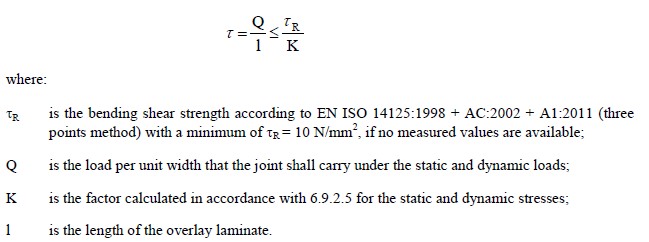
The shear strength between the overlay laminate and the tank components to which it is bonded shall
not be less than:
Openings in the shell shall be reinforced to provide at least the same safety factors against the static
and dynamic stresses as specified in 6.9.2.5 and 6.9.2.6 as that for the shell itself. The number of
openings shall be minimized. The axis ratio of oval-shaped openings shall be not more than 2.
For the design of flanges and pipework attached to the shell, handling forces and the fastening of bolts
shall also be taken into account.